The TemperatUHR Project
The story and an introduction to the "TemperatUHR" project, a smart temperature measuring station for the connected home.
The project idea
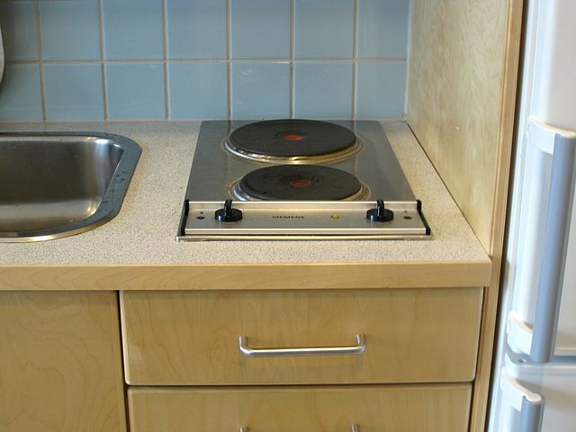
Many people know the problem: you just want to quickly cook some pasta, but then find yourself in a kitchen with an antiquated solid hotplate that takes forever to heat the water.
When the Paul Award was announced at the end of 2019 by the FED, the professional association for design, PCB, and electronics manufacturing in cooperation with the trade magazine "Elektronik Neo", I chose this problem as the topic for my project submission. I named the project "TemperatUHR" so that the connection between temperature and the time component would be clear right away. My project goal was to solve the problem of having to wait a long time for temperature changes in liquids (and theoretically gases, although these usually change temperature more quickly) by means of a small measuring station and a corresponding app.
The development of the "TemperatUHR": Hardware
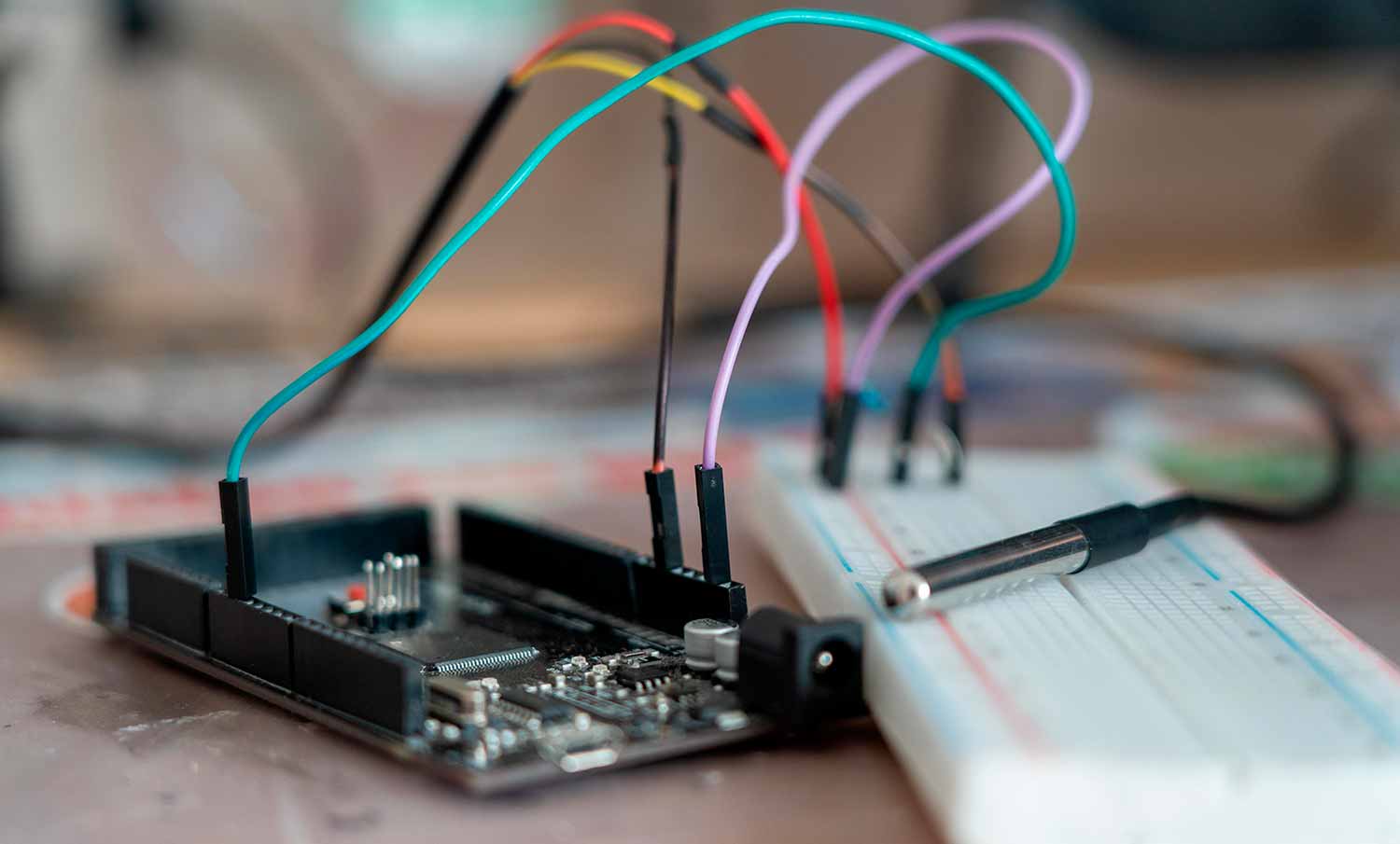
Since one of the goals of the competition was to develop a printed circuit board, this was one of the first tasks for me: after successfully testing the functionality of the temperature sensor (a highly accurate DS18B20 12-bit sensor with low power consumption) with an Arduino Mega 2560, I began designing a PCB. It was supposed to be small and easy to manufacture. My original plan was to develop the PCBs at the RaumZeitLabor in Mannheim, but I had to abandon that plan due to material and quality problems.
But before I could begin designing the PCB, I first had to create a circuit diagram:
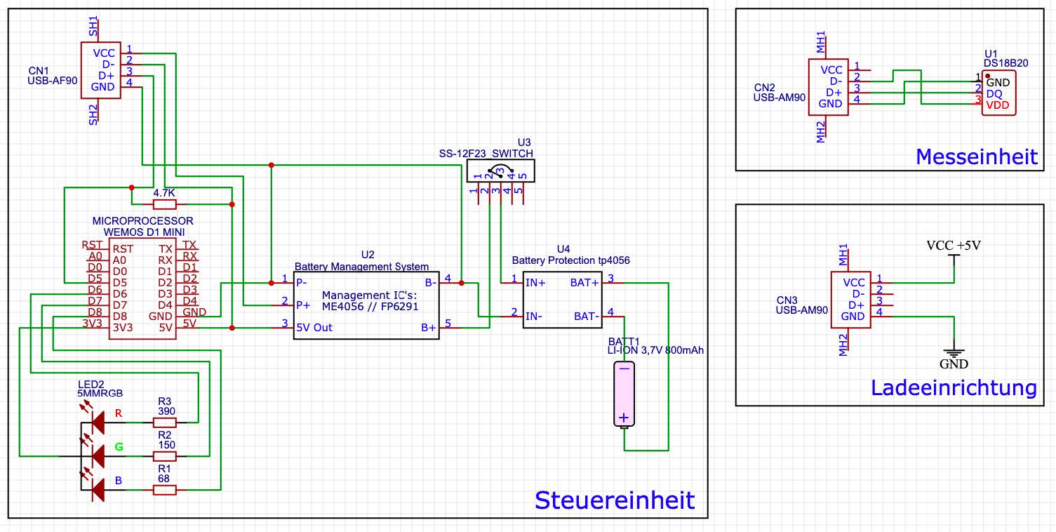
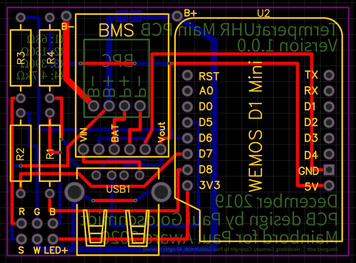
Once the circuit diagram was finished, it was finally time for the PCB design:
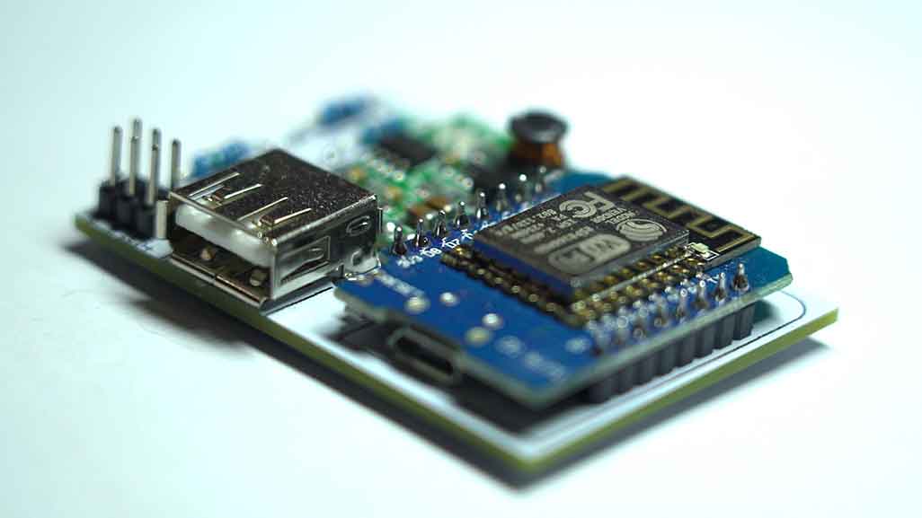
In just 55 mm * 40 mm, I managed to fit the entire charging electronics, the microcontroller, all series resistors, a USB connector, as well as pin headers for tapping the LED voltages and the on/off connection. I largely avoided SMD components so that even people without much soldering experience could easily recreate the project. However, the tolerances were so tight that making it myself became practically impossible. So I sent the Gerber files to a PCB prototype manufacturer so that the PCBs (including solder mask) could be produced properly.
Eight days later, the mail carrier rang the bell and delivered a package containing 10 of the PCBs.
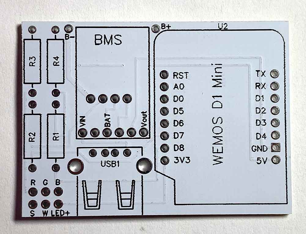
So it was time to solder the components onto the PCB, as always starting with the smallest components and working up to the large main processor:
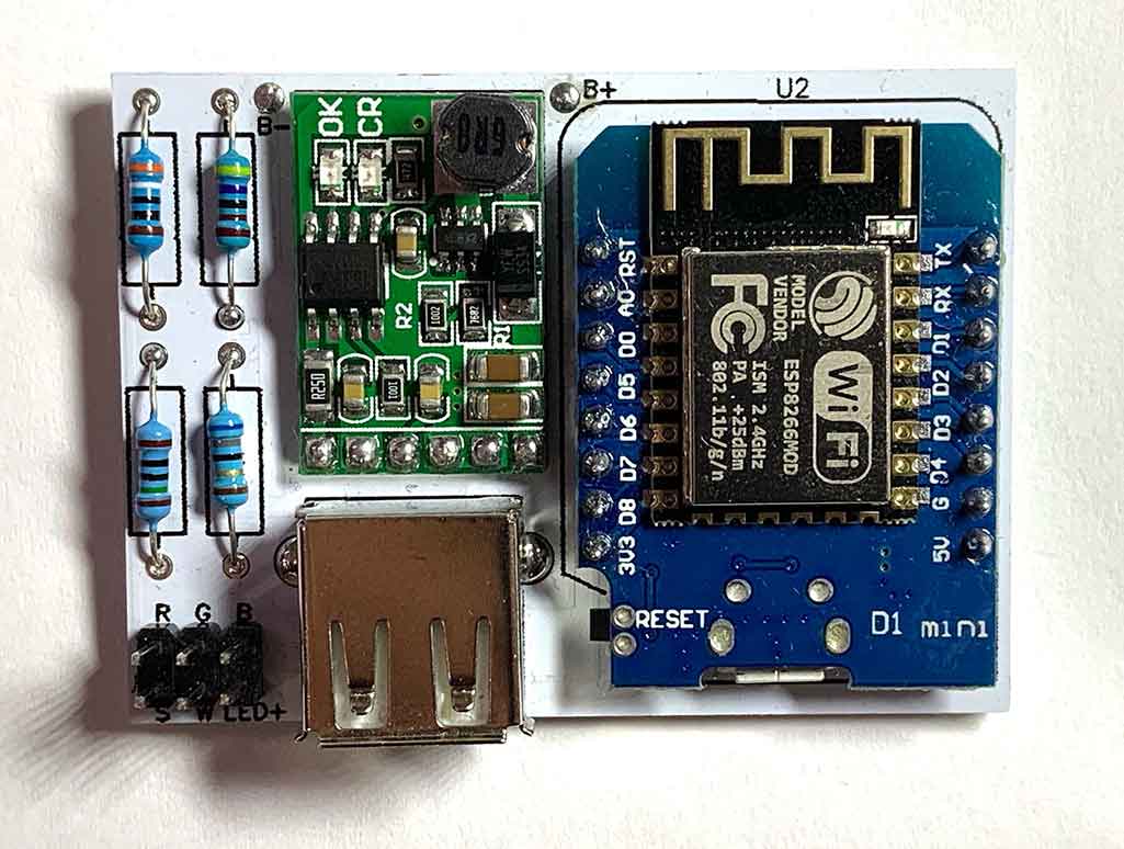
Once the first PCB was fully assembled, it was finally time for
Software development
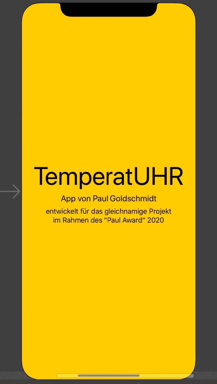
The first question was which programming languages I wanted to use for the project. As a test, I started developing an app in Apple's native programming language, Swift.
At the same time, I tried out SwiftUI as a user interface design tool, but I dropped the idea of a native Swift application after the limits of Apple's power-saving features in iOS would not have allowed all of the app's planned functions. So I looked for alternatives for smartphone communication with microcontrollers and ultimately found what I was looking for in the IoT platform "Blynk": the platform, which was free for this use case, had the major advantage of cross-device compatibility, so after the Swift app I would not also have had to develop an Android app in Java. In addition, the integration with a microcontroller was simple and clearly structured. So I began developing the software in parallel in Blynk for the smartphone and in C++ for the microcontroller. In total, around 400 lines of code on the microcontroller side were enough to implement the app connection. In addition to the app connection, an over-the-air (OTA) update function was also integrated so that new software could be uploaded to the sensor unit without opening the housing.
After communication between the microcontroller and the app worked reliably, one final project step remained before development was complete:
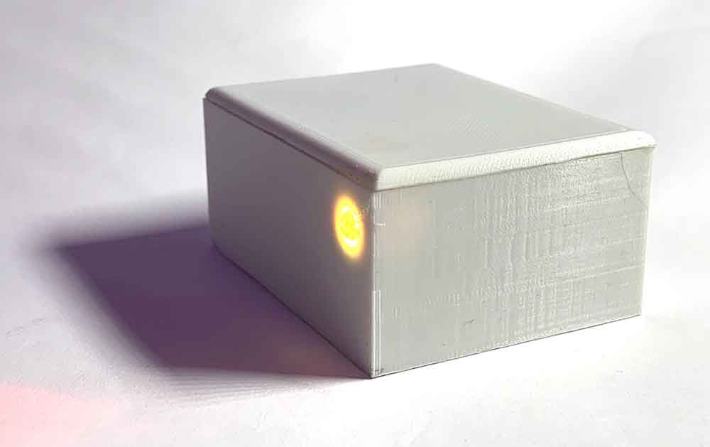
The final assembly
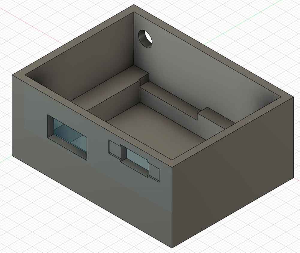
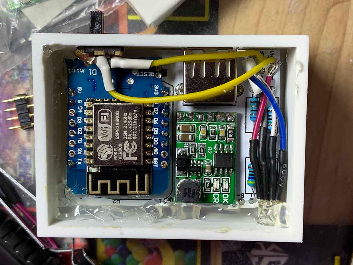
To complete the project, it was time to develop a housing for it: using the dimensions of the battery, the PCB, the LED, and the power switch, I designed a suitable housing in the CAD software Fusion360, which I printed from PLA on a 3D printer. To protect the electronics from vibrations, I additionally lined the underside with a synthetic fabric.
After that, I first placed the battery and then the PCB into the housing. The PCB was additionally secured with adhesive inside the lined housing.
The end result

Once the project worked as such, I completed the documentation for GitHub so that the project could be easily recreated by following the instructions. The GitHub repository
The project received an award at the end of November 2020 during the closing event, after it had to be postponed several times due to the coronavirus pandemic. The closing event at the end of November was then held digitally; in addition to the participants in the project, the entire jury was present. The project received first prize for its excellent reproducibility, a good concept, and complete project documentation. The open-source aspect of the project was also especially praised.
As part of the award ceremony, a press release was published by the FED:
For the closing event of the competition, I also produced a video that briefly explains the project:
Acknowledgements
Finally, I would like to thank the FED and the sponsors of the competition for organizing and financing the event. The competition offers young people in electrical engineering a rare opportunity to present projects publicly and work on their own skills.
Background: The PAUL Award
The first PAUL Award was announced in 2019 by the FED e.V., dem Fachverband für Design, PCB, and electronics manufacturing. The cooperation partner was the trade magazine Elekronik Neo, and sponsors included Viscom and Technosert Electronic.
The industry award for young electronics enthusiasts was aimed at school pupils, students, and young professionals between the ages of 15 and 25 who enjoy electrical engineering and electronics. A total of 19 different teams and individual participants from the German-speaking region competed against each other. A jury evaluated the submitted project results based on criteria such as creativity, technical understanding, and the quality of the project outcome, and determined three winners.
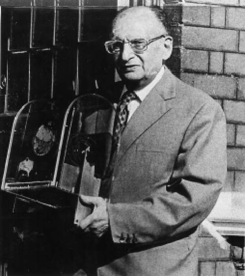
The prize was named after Paul Eisler, an Austrian engineer and the inventor of the printed circuit board; the next PAUL Award will be announced on January 21, 2021.