Apple HomeKit with the ESP8266 in One Evening: Making a Dropshipping Light Picture Smarthome-Compatible
For just under 15 euros, you can get light pictures from well-known dropshippers that gain their charm through backlighting. Unfortunately, the lighting can only be changed via a cumbersome inline cable remote. Time to change that and step into the world of Apple HomeKit.
The Beginning
I have to admit: sometimes I let marketing and product photos tempt me into impulse purchases. Especially on Instagram and X/Twitter, you occasionally find, alongside product images and definitely not AI-generated ad copy, links to some shady dropshipping companies based in Bottropp or the Seychelles, which in the background are also just placing the orders on AliExpress or Alibaba, the wholesale marketplaces for direct shipping from China. Every time I see an ad for a product that makes big promises about the product and rather less impressive promises about customer support, should something go wrong on the thousands of kilometers from China to Germany, I first check what the product costs directly "one level higher" on AliExpress. In the case of a light picture, meaning a backlit piece of art, which was offered to me in the "biggest sale of the year" on a small dropshipping site for "only" 59 euros, I found it directly on AliExpress for a mere 15 euros including shipping. And at that price, even I gave in: if this product was even half as good as it looked in the pictures, I would be more than satisfied with my purchase.
A good 15 days later, when the light picture was delivered in a broken package with a cracked frame (nothing a bit of all-purpose glue couldn't fix), I was able to take a first look at my impulse investment after repairing the frame: when switched off, a plastic frame in a wood look with black lines on a white surface; with the backlight on, colored accents and surprisingly convincing shadowing. And even though the colors are nowhere near as intense as in the original, I was quite happy with that part of the product. I was less happy with the manufacturer's decision to place an inline remote between the picture's USB plug and the frame for control, which was both inflexible and awkward to use, especially if the cable was supposed to be hidden as much as possible. Not to mention possible time-of-day-dependent automations or more than two gradations in color selection. A light picture like this would actually be a perfect product for smart home integration, but for reasons unknown to me (probably to save a few cents in production), there are no products on the market that offer this. But since it was clear that I wouldn't use this otherwise really great artwork with the built-in remote, it quickly became obvious that I would have to help out with the smarthome integration myself. A quick Google search shortly afterward revealed that with Wi‑Fi-capable microprocessors, especially the ESP series from espressif, integration into the Apple HomeKit ecosystem would be possible, even if many of the libraries hadn't received updates in years. In any case, there were more than enough clues to make the upgrade seem at least somewhat realistic.
An Evening Project
Since after my move to beautiful Hamburg I currently hardly have any access to my little workshop, it was also clear that this smarthome retrofitting shouldn't turn into a project lasting several days. Instead, I made a plan to complete the conversion in one evening. As a result, I could only use components that I still had in stock from other projects and that I roughly knew how to use. At that point, however, I had no idea how the light picture was built internally or what kind of control was used to drive the LEDs.
To break a bit from my classic project report format, dare a stylistic shift, and try something new, I'll now tell the story of the retrofitting chronologically and divided into four eras.
I: Before 8 PM
"So, how does this work here and which components do I have in stock?"
It is 5:15 PM. After six hours and six minutes of driving from Hamburg to Heidelberg, I arrive at my former home in light rain, the place where my little workshop is still located. At the moment, it serves more as storage space and less as a place for tinkering and building. I had actually wanted to go for a run in the last rays of the now much weaker autumn sun, but the rain put a stop to that plan.
So I start by clearing off the workbench and (as one does) simply putting everything that is currently lying on the workbench onto another free surface, which mostly means the floor. I test the light picture, which apparently survived the trip from Hamburg to Heidelberg, one last time with the remote and immediately turn to taking it apart. This turns out to be very simple because the back panel, a thin MDF board, is held in place only by a few metal clips.
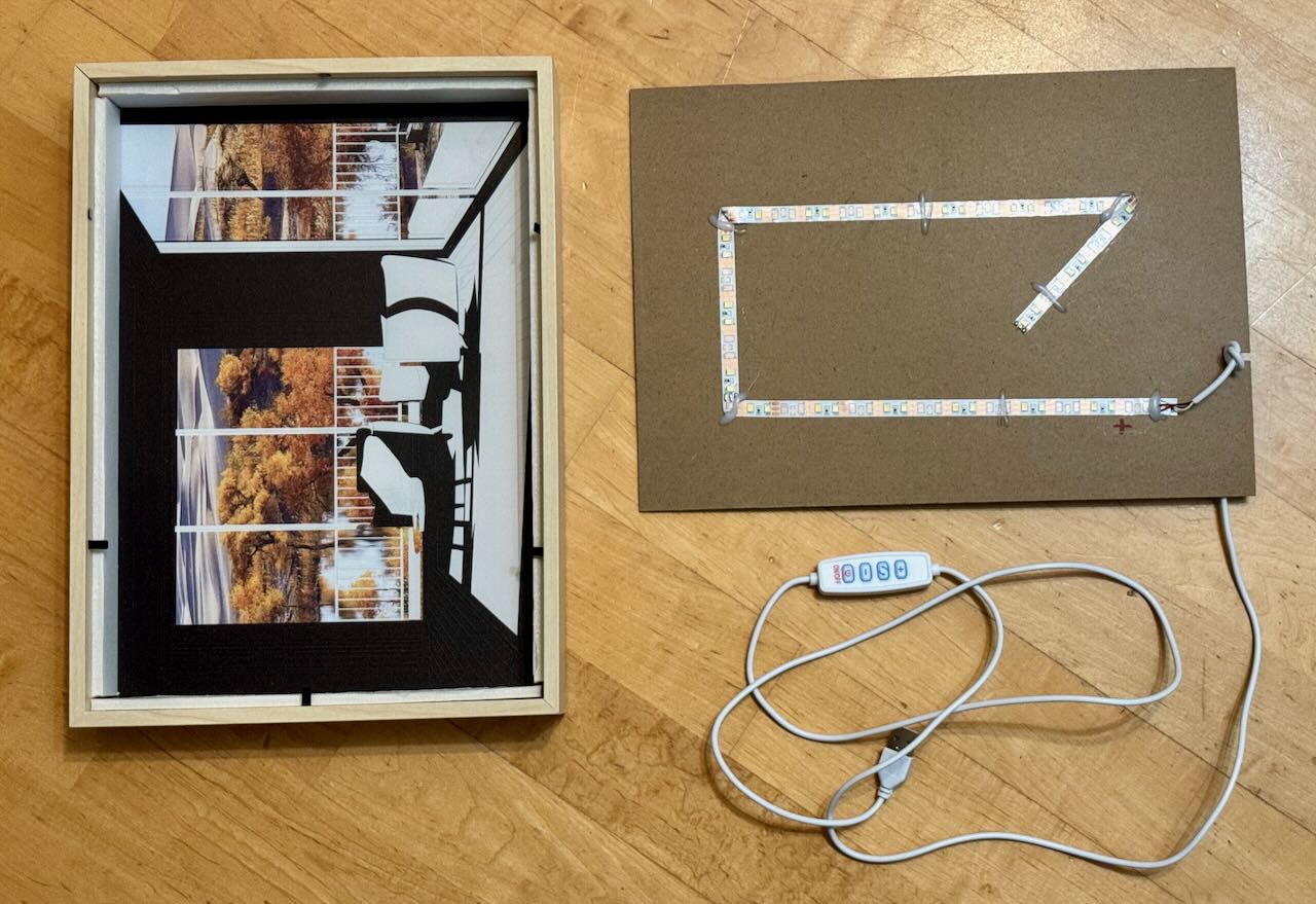
A first look inside shows the pure focus on maximum cost efficiency and the brutally simple design of the components. One cable, one LED strip with two white LED color temperatures, and a lot of air. Opposite the MDF board sits the actual picture, divided into three layers: cardboard that blocks light in certain places, then a translucent color print projected onto the frontmost layer, a wafer-thin acrylic frosted panel with a printed line pattern. The frame consists of plastic in a wood look and a thicker white piece of foam, which is probably meant to reflect the light internally as well as possible. All in all, I would estimate the material cost at a maximum of two euros, more likely one. Even with shipping from China for this A4-sized light picture, which certainly isn't exactly cheap, you probably end up in the high single-digit euro range. Paying 15 euros for it was probably fair; paying 50 euros like other sellers charge for the exact same product is sheer extortion.
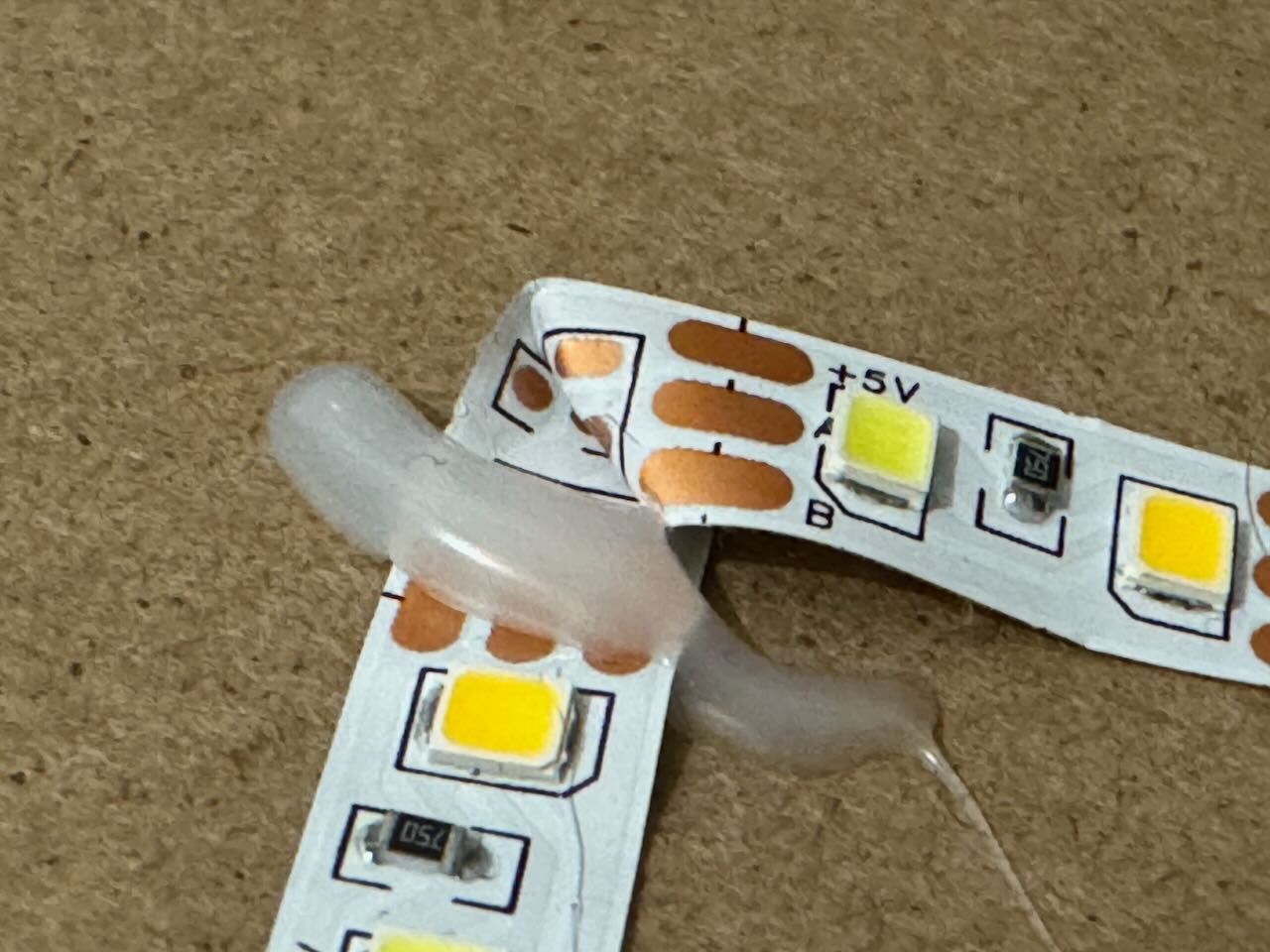
The LED strip with its two individually controllable white temperatures is driven directly by the remote at 5V with a common anode using a very ugly PWM signal for control and dimming, and the way the LED strip is simply folded around corners and held in place with hot glue is, from a product safety and longevity perspective, about the most absurd idea I have seen in a long time.
And even though I am not particularly convinced by the physical construction inside the light picture, the simplicity has at least one major advantage: I can simply connect directly to the LED strip with a microcontroller and treat it as a simple analog output instead of having to program the LEDs themselves (as with digital LED strips such as those based on WS2812B LEDs).
So I take a look into my box of components and pull out an ESP8266 chip on a so-called NodeMCU V2, a breakout board with a few conveniences, such as the option of direct 5V power supply. I also take out the bag of transistors and MOSFETs with which I could then drive the LEDs.
II: 8 PM to 10 PM
Bored MOSFETs and stressed software development
I decide to use IRLZ44N MOSFETs from Infineon Technologies to drive the LEDs. For one thing, with a maximum switching load of almost 80 amps, I don't have to worry about overheating transistors in TO-92 packages, and for another, I still have quite a few of this type left over from my very early experiments in electrical engineering (around 2014). And even though I feel a little sorry for these MOSFETs, which are of course completely absurdly oversized for this purpose, at least they have a long life ahead of them thanks to the very favorable operating conditions.
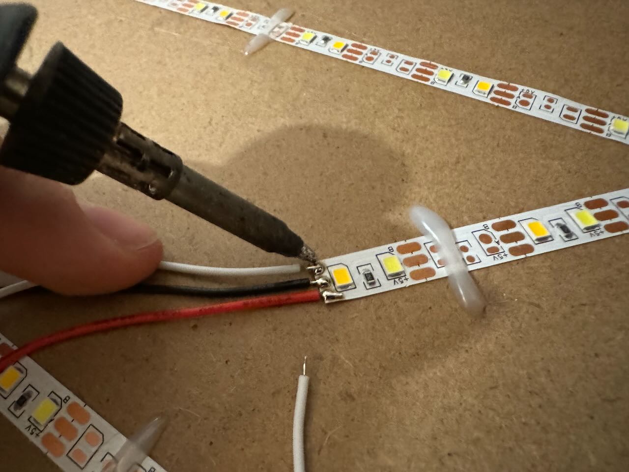
So, time to heat up the soldering iron and solder a few jumper wires to the LED strips: after these are now connected to a breadboard and a test setup has been built, exactly nothing happens on the first power-up (drumroll please). At least 30 minutes later, after an oscilloscope analysis of the microcontroller's control signal, the cause of the error becomes clear: I simply do too little prototype development these days! Not a loose contact or a broken component, but the fact that I had forgotten that the power-carrying connected side rails on a breadboard are interrupted in the middle is what caused it not to work. In the meantime, I work meticulously on the software, which also presents me with its own challenges. These primarily arise because the library is no longer compatible with Apple HomeKit out of the box and therefore needs a few adjustments: in particular, many (older) examples are missing the code snippet
arduino_homekit_setup(&accessory_config);which announces the configuration on the network or to Apple HomeKit every time the microcontroller starts. If this is missing in the setup, no data is transmitted anymore after a reconnect following setup in Apple Home.
III: 10 PM to Midnight
Let There Be Light!
What is particularly exciting for me in the software is also how the functions of the HomeKit accessory are defined in the hardware layer: in the end, the various properties are set as feature flags for each device; on the internet I couldn't find an example of self-developed HomeKit accessories that control LEDs only via white color temperature. So I set out to search for the correct feature flag myself in order to set "HMCharacteristicTypeColorTemperature" in HomeKit. While looking through the library source code, I then find "cha_color_temperature" as a possible feature flag, which gives me values from 50 to 400 micro-reciprocal degrees (mired) back in the program. Mired is the reciprocal of the more familiar color temperature specification in Kelvin; the following applies:
[katex]text{Mired value} = frac{10^{6}}{text{Color temperature in Kelvin}}[/katex]
After working on the software a bit and wanting to test it for the first time, I turn back to the control circuit, which is still not working. I fix it by wiring the breadboard correctly (what a miracle that a wrongly assembled breadboard doesn't work properly).
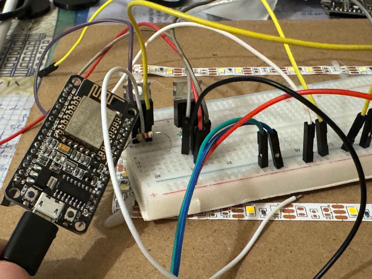
Before connecting the LEDs for the first time, however, I first check with the oscilloscope whether the control works as desired. That the connection works and the microcontroller interprets the values correctly becomes apparent here:
https://p3g3.de/content/media/2026/04/prototyping.mp4
Perfect! Communication between Apple HomeKit and the ESP works. A few hours ago I wouldn't have thought this would be so easy; after all, Apple is very restrictive with its technologies, so I wouldn't have expected it to be this simple to hook into it with an ESP dev board. But there is still a lot of optimization work to do: the LEDs are mapped incorrectly in the control logic, and the whole software is still very bloated with unnecessary function calls that slow down execution and refresh rate unnecessarily. So: optimize and simplify as much as possible.
IV: After Midnight
"Integration hell is no joke"
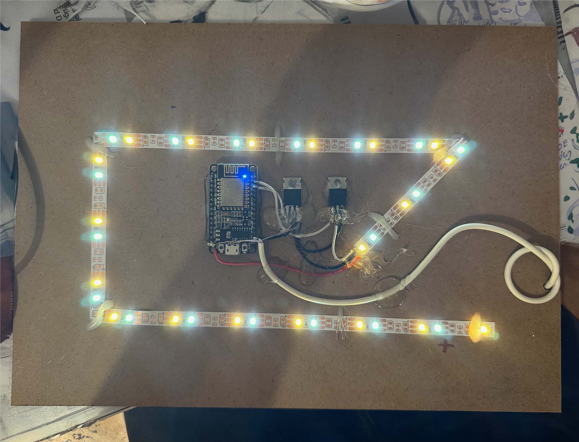
In every project, whether it spans several years and billions of dollars (like car manufacturing) or is a one-evening bit of fun, at some point everyone faces the step of integrating what has been built. In this project, the integration work mainly consists of moving the flying setup from the breadboard into the frame, which, as so often, turns out to be much more involved than expected. It's not for nothing that people often speak of integration hell, because in this step many necessary optimizations become apparent once again. In any case, I start by removing the jumper wires and replacing them with lower-resistance copper wires, which I cut to the correct length in the same step. Then I do something that makes some electrical engineers' toenails curl: I glue (!) the IRLZ44N MOSFETs to the thin MDF back panel with hot glue. I would never recommend this approach to anyone in any situation; from a maintainability and safety standpoint, gluing components like this is pure horror. That's why I double-check that my MOSFETs do not get even slightly warm (I calculate the maximum power dissipation at about 0.1 watts per MOSFET in the absolute worst case, plus about 0.01 watts from each pull-down resistor. That is not remotely enough power dissipation to raise the MOSFET even one degree above room temperature—but still: if you are not planning to finish a project in one evening, if other people may ever come into contact with what you built, and if you cannot be absolutely certain that the heating of the glued components is negligible, adhesive is the wrong option.
After gluing the MOSFETs in place, I shorten the pins of my NodeMCU microcontroller and glue it directly next to them. It is wired to the MOSFETs, then a new USB cable follows, which I immediately cut to the required length. This is then connected directly to the MOSFETs; with a thin wire I also sort out the microcontroller's power supply (which, by the way, operates entirely on a 3.3-volt level; I can only connect 5V directly because the NodeMCU has an internal voltage regulator from 5 volts to 3.3 volts and can therefore handle the supply voltage. The logic level at the MOSFETs is of course still 5V) and then route the USB cable out through the opening in the back panel with a knot in front of the opening as strain relief.
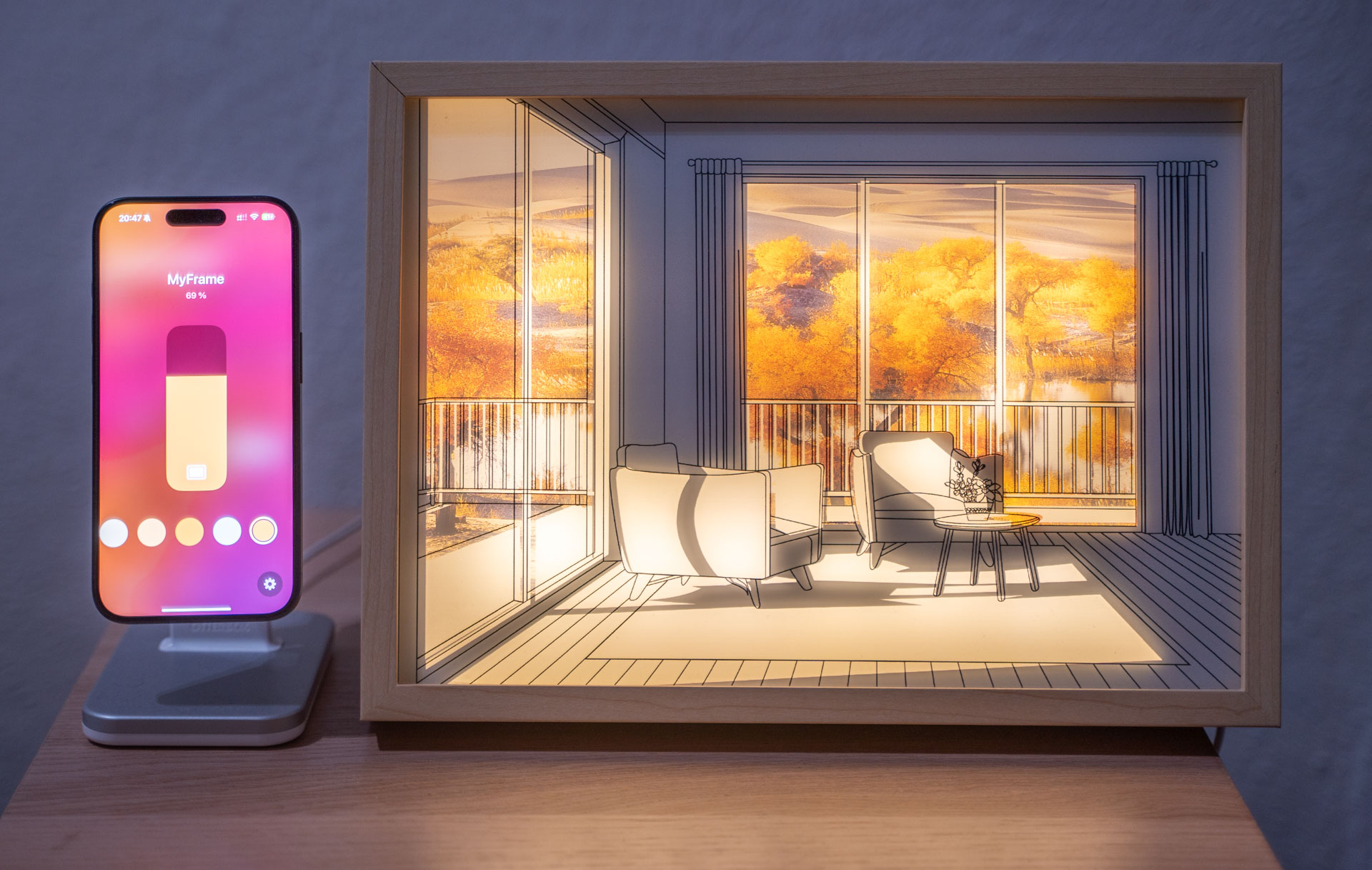
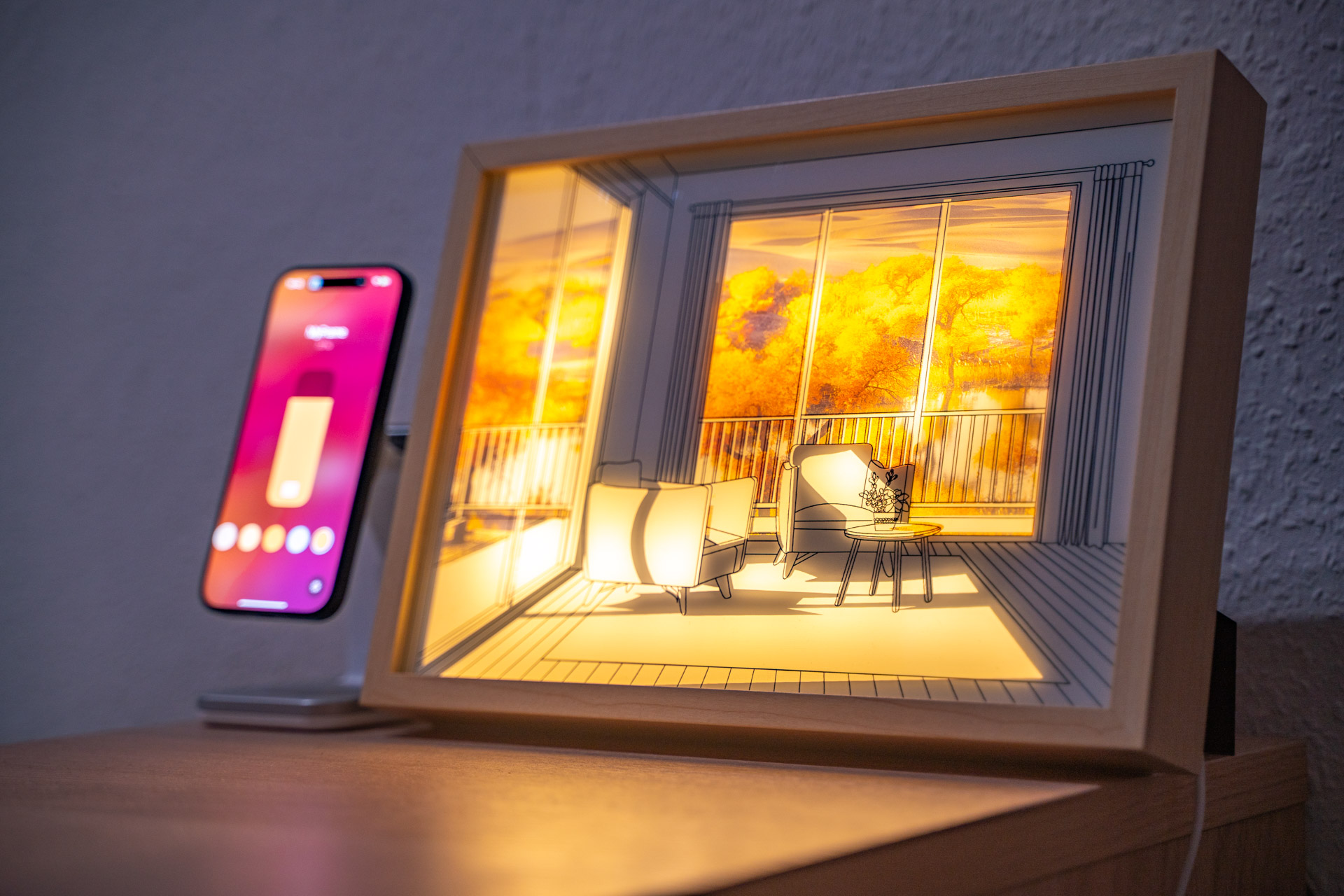
The Result
After around six hours of trying things out, soldering, and writing software, it was done: my light picture with a retrofitted Apple Home connection. I chose MyFrame as the project name, because with the integration, some random framed light picture really became my framed light picture. I couldn't be happier with the functionality: now the light picture turns on every time I come home and turns off again when I leave the house. The course of the sun is also simulated thanks to Apple HomeKit and a third-party app from Eve Systems, which lets you create the routines needed for this simulation for all HomeKit devices. The blog "Smartapfel" explained how this works in an article.
https://youtu.be/pyPz1fwxYl0
And now you!
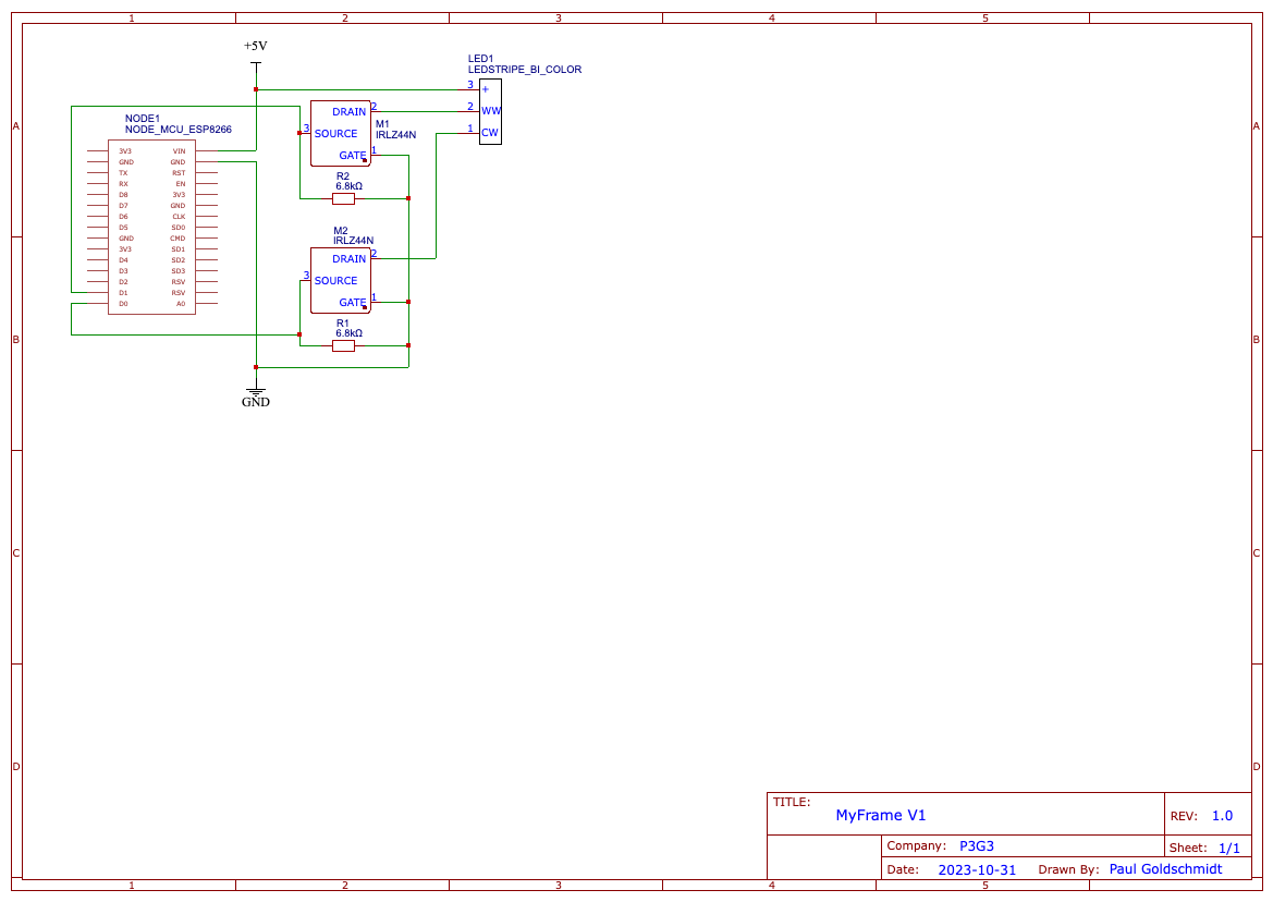
After finishing it, I published the software as well as a small circuit diagram on GitHub. The repository also contains a copy of the library, so it can be installed directly.
If you don't just want to replicate the project but want to develop something in that direction yourself, I would recommend taking a look at the file
/src/homekit/characteristics.h
in the HomeKit library. All Apple HomeKit characteristics are implemented there, directly with the maximum values that can be passed to your program.
Ideas for the Future
This project opened my eyes to how much is possible with self-developed accessories for Apple HomeKit: from playful lighting ideas to irrigation projects and deep home automations, there is a lot that I would still love to try out. The concept of the light picture also really hooked me; I would love to build a larger light picture myself. But the planning for that is still at a very early stage, especially because generating the data for the motifs is not simple. If anyone feels called to work on the topic with me and build a light picture in A3 or even A2 size for even more "wow factor," feel free to get in touch here. In any case, it was huge fun to dive back into hardware development after some time and other projects like the TemperatUHR project - definitely something I would love to repeat again in the near future. There are enough ideas on my site.